variable speed drive diagram
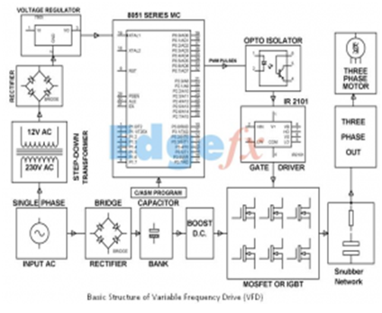
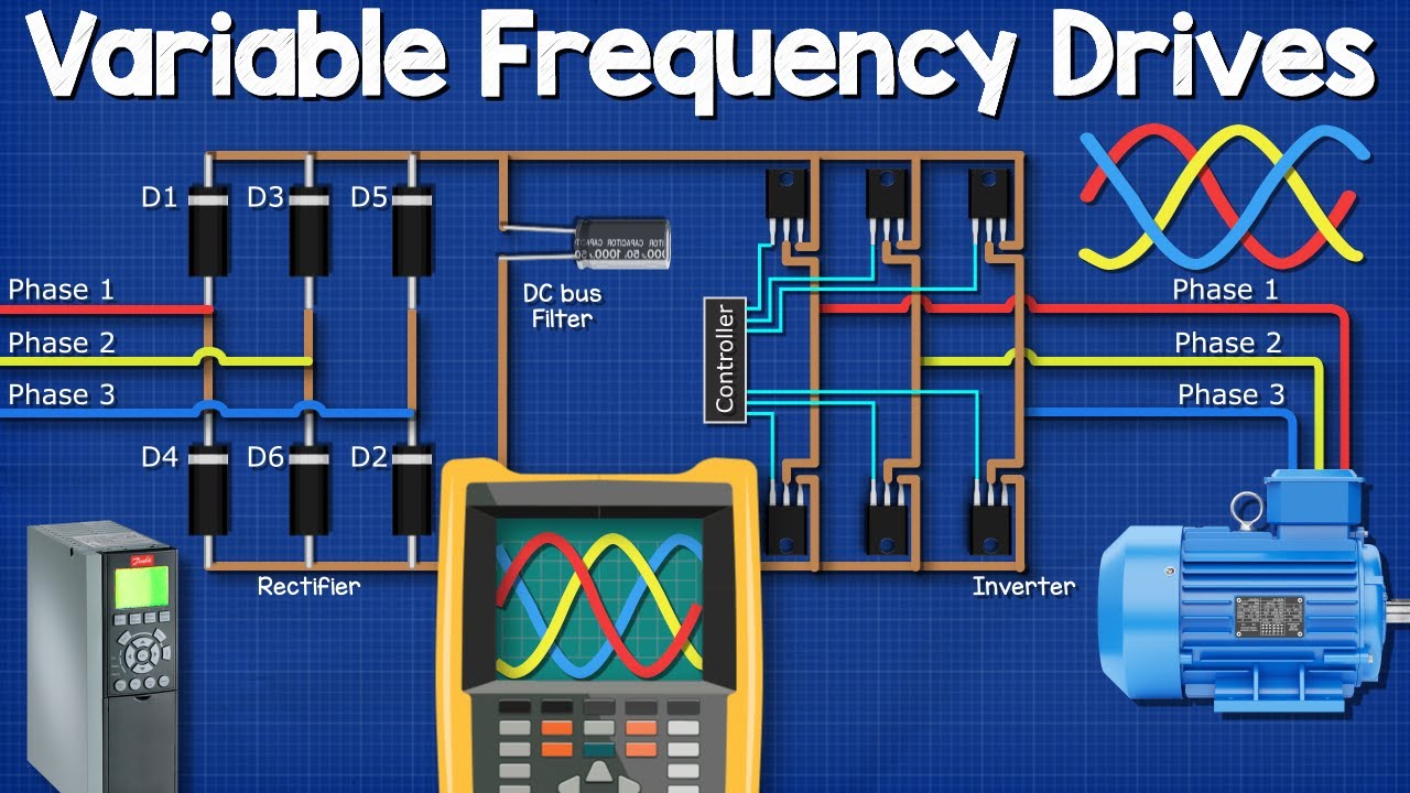
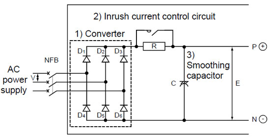
The examples and diagrams in this manual are included solely for illustrative. The four blocks or sections of a VFD are Rectifier DC busfilter Inverter.

Variable Speed Drives An Overview Sciencedirect Topics
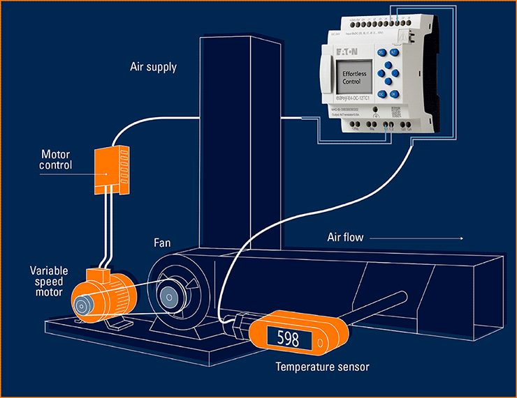
Lowest speed of fan is set 10Hz temporarily and it is variable speed drive.

. An Operator Control a Drive Controller and. The packaged line filter lowers THD-I better than just a line reactor used alone. Variable speed drive sets speeds of 5 stages according to above table and speeds are required to be adjusted.
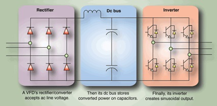
4 Processes and their requirements Variables in processing systems This diagram shows what kinds of variables affect the. MTD B Variable Speed Pulley Assembly. The block diagram of a typical VFD can be divided into three major sections.
If the supply power is in AC form VSDs utilize a rectifier circuit to convert the AC to DC at a specified. And it helps protect the VFD from line. The variable speed drive calculates the motors required voltage and current.
DC power is then fed into an inverter producing AC power at the precise voltage and current needed. The power-conversion section. The primary purpose of the drive is to convert the 5060 Hz AC input voltage into a variable frequency variable voltage output to power the variable speed scroll compressor.
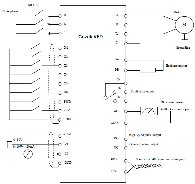
Ground wires must be copper only and sized per the NEC. It has three main components. 10 Guide to variable speed drives Technical guide No.
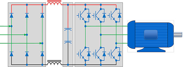
It has three main components. This can be accomplished by turbines direct current motors variable speed motors or slip-ring motors. The below block diagram illustration depicts a typical three-phase AC variable speed drive system.
Check the manufacturers diagrams for the most accurate information. Variable Speed Drive VSD must be grounded in accordance with the 2017 NEC Paragraph 250118. The below block diagram illustration depicts a typical three-phase AC variable speed drive system.
Variable speed drives supply specific amperage and voltage to a motor. The fan output capacity and pressure can be varied with the. Driveswarehouse - AC Drives DC Drives Variable Frequency With more than 50 years of experience in variable speed.
Circuit Diagram of VFD Generally a VFD is made of four blocks or sections where each section has its own function. Refer to Table 250122. To give you mechanical and electrical information related to the Altivar320 drive to show.
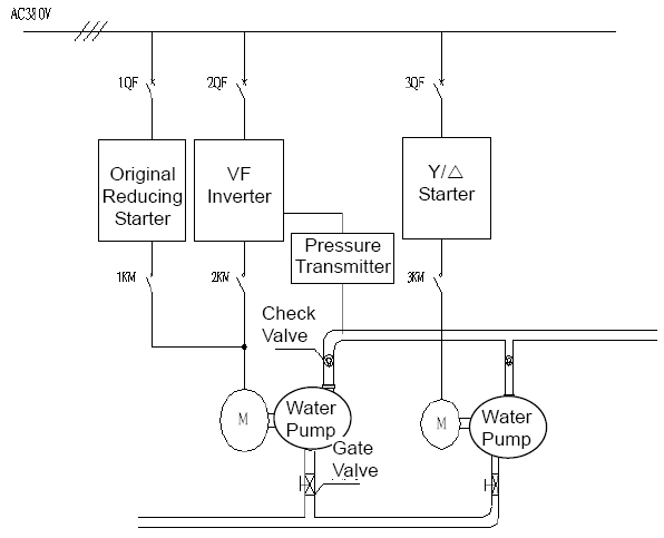
Variable Speed Drive Series C 03740 kW 055 HP FRN 703 FRN 704 FRN 705 FRN 706. NVE41289 012017 9 About the Book At a Glance Document Scope The purpose of this document is. Variable speed drives control duplex pumps Advantages Reduction in.
Each variable speed drive is supplied with an installation manual.

Variable Frequency Drives Explained Vfd Basics
Introduction To Variable Frequency Drive Controller For Induction Motor
Variable Frequency Drive On Refrigeration Compressor

What Is Vfd Working And Block Diagram Of Variable Frequency Drive

Variable Frequency Drive Wikipedia
Frequency Inverter Frequency Changers Adjustable Frequency Drives Afd Variable Frequency Drives Vfd Variable Speed Drives Vsd Manufacturer In China Brosea Electric Limited
Variable Frequency Drive Vfd Manufacturer Supplier In China
Variable Frequency Drives Explained Vfd Basics Igbt Inverter Youtube
Brief Explaination About Working Of Vfds Benefits And Application
![]()
Variable Frequency Drives Explained Vfd Basics

Variable Speed Drives An Overview Sciencedirect Topics
Variable Frequency Drive Working Principle

3 Phase Induction Motor Control Using Variable Frequency Drive Vfd Elex Focus Electrical Circuit Diagram Circuit Components Electronic Engineering

Siemens How To Design A Variable Frequency Drive Vfd Panel
A Review Of Variable Speed Drive Technology Part 2 Pumps Systems

Variable Frequency Drive Wikipedia
Variable Frequency Drive Basics Working Principle
Vfd Control

Vfd Definition And Explanation Youtube